

|
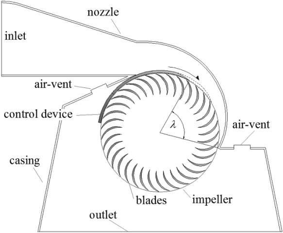
A new prototype of Cross-Flow micro-turbine, based on an efficient discharge regulation, has been designed, constructed and tested in the labs of the University of Palermo (Italy). The turbine is aimed to replace the valves at present used for discharge and pressure regulation by means of energy dissipation and to convert the lost energy in electricity. Discharge regulation can be obtained by means of a circular segment rotating around the axis of the impeller. The segment position can be set in order to change the inlet surface of the same impeller (see Fig.1). Observe that the shape and the location of the blades are fixed.
|
 |
| It can be shown that the efficiency of the turbine is strictly related to the relative velocity Vr at the inlet, i.e. to the ratio between the norms of the water particle and of the reference system velocities at the impeller inlet, and that its optimum value is about two. It can also be shown that the inlet velocity is mainly function of the water head immediately before the turbine and of the impeller angular velocity. By using an asynchronous generator, with an almost constant impeller angular velocity, it is possible to save the optimal relative velocity at the impeller inlet by changing the inlet surface according to the sought after discharge. The variation of the head losses occurring in the pipe before the turbine, due to the discharge change, is assumed to be small.
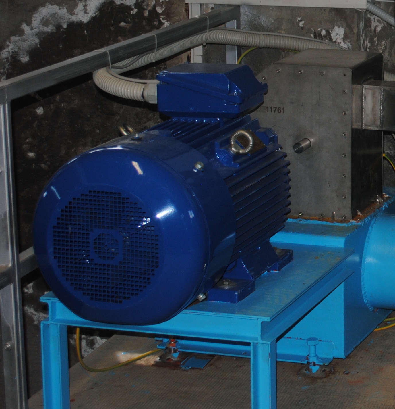
If discharge variability is due to the variability of the natural source, the aqueduct final valve is aimed to guarantee a positive pressure inside the pipe with all discharge values. In this case the position of the segment is set according to the pressure measured before the turbine in order to maximize the produced power, proportional to the head and to the discharge. Discharge is related to the same head through the turbine characteristic curves. A turbine prototype (without control device) has been already constructed and tested in the lab of the University of Palermo (UNIPA) and a second machine (with control device) has been already placed in the urban tank of a small Sicilian town, at the end of a 2.5 km aqueduct. Three other pilot plants should be constructed and installed before the end of the year. The experimental plant at UNIPA has a dynamic torque installed between the impeller and the axis of the generator, so that the outlet power of the machine is known. By measuring the power of the flow rate entering in the turbine it is possible to measure the efficiency of the machine for different l angles (see Fig.1). The maximum inlet l angle is 120°. See in Fig. 2 the efficiencies computed by means of CFX analysis and measured in the Palermo lab. See in Fig. 3 the efficiencies, computed by means of CFX analysis, for the machine installed in the pilot plant. For each discharge value the hydraulic head before the turbine has been kept constant by the segment regulation. Observe that the l variation is almost linear along with the discharge, according to the hypothesis of constant velocity for constant hydraulic head. Efficiency remains above 80% for a discharge range between 3 and 10. It can be shown that the same minimum efficiency can be guaranteed with an even larger range by increasing the number of blades and reducing their thickness, along with their inner/outer diameter ratio. |
|
|
|
|
|
Observe that, because the loss of energy per unit length of pipe is proportional to the inverse of the fifth power of diameter, the new generation of pipes replacing the old ones will allow a large energy saving with a small additional investment. The capital return time of the 10 KW constructed prototype, crafted by a small company, is of the order of 1 year. |
 The amount of energy lost in hydraulic infrastructures, carrying water from natural (springs, wells or rivers) or manmade (artificial basins) sources to tanks and from tanks to the distribution network, is much larger than the amount of energy strictly needed for water pumping from lower to higher levels. Most of this energy is at present lost either during transportation along all the pipes or locally, in valves placed specially at the end of aqueducts for discharge regulation. For example, an aqueduct carrying 1 m3/s from a source 100 m higher, has a gross power loss of about 1 MW.
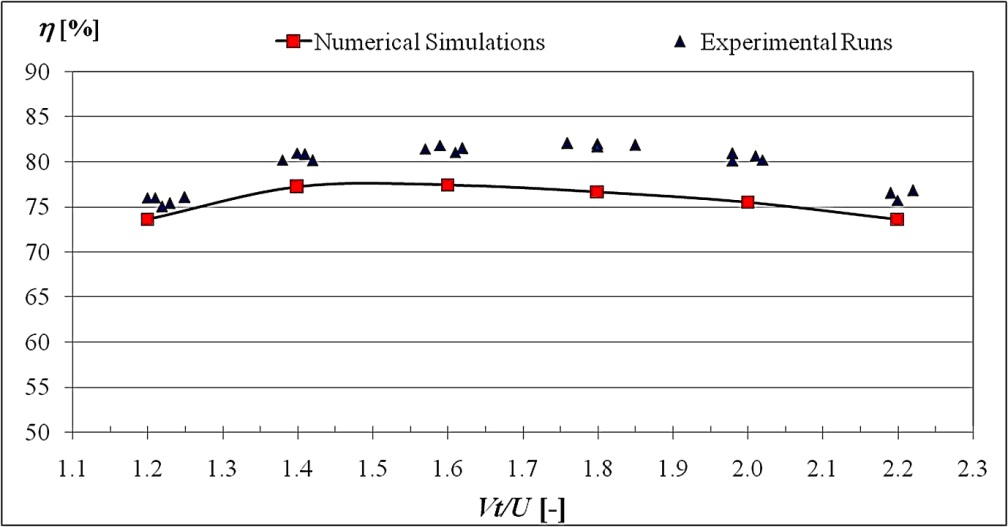
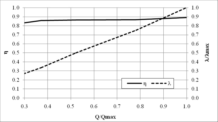 Figure 3. Efficiency and l curve of the pilot plant turbine (with regulation)
Per ricevere quotidianamente i nostri aggiornamenti su energia e transizione ecologica, basta iscriversi alla nostra newsletter gratuita
e riproduzione totale o parziale in qualunque formato degli articoli presenti sul sito.


